Wavelength & Electrical Length Calculator
Convert between frequency f [Hz] and wavelength λ [m] in vacuum or in any medium by setting relative permittivity εᵣ and relative permeability µᵣ. Then compare the physical length L [m] of a conductor — cable, wire, or PCB trace — against that wavelength to identify its operating regime: electrically short (lumped-element model holds), distributed (transmission-line effects matter), or resonant (efficient radiator).
Note: For microstrip and cables consider to use εreff, not just εᵣ of the dielectricum (e.g. FR-4, PTFE, etc.)
εr
μr
VF
Vp
FREQUENCY
Hz
kHz
MHz
GHz
THz
WAVELENGTH
km
m
cm
mm
μm
PHYSICAL LENGTH L
mm
cm
m
mil
in
ft
ELECTRICAL LENGTH
L / λ
Equivalent
EMC regime verdict ↓
EMC EVALUATION
< λ/10
Electrically short
λ/10 - λ/4
Distributed effects
≥ λ/4
Potential efficient radiator
Type in any field — all other fields update automatically.
Quantities:
-
λ — wavelength in the medium. The yardstick for electrical length: a conductor stops behaving as a lumped element once L is no longer ≪ λ. This is the number the EMC evaluation compares against.
-
εᵣ, μᵣ — relative permittivity and permeability of the medium. For virtually all PCB and cable dielectrics μᵣ = 1; only ferrites and magnetic loading make μᵣ ≠ 1.
-
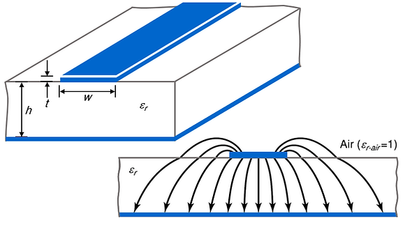
εr,eff — effective permittivity. On inhomogeneous lines (microstrip, coplanar waveguide) the field travels partly in the dielectric and partly in air, so the line behaves as if embedded in a single uniform medium with 1 < εr,eff < εᵣ. Enter εr,eff in the εᵣ field when working with such lines — using the bare substrate εᵣ overstates the slowing and flags resonance too early. For fully filled geometries (stripline, coax) εr,eff = εᵣ. Note εr,eff rises with frequency (dispersion), approaching εᵣ in the GHz range.
-
VF — velocity factor. The fraction of c at which a wavefront travels in the medium: VF = vₚ/c = 1/√(εᵣ·μᵣ). Useful sanity check against datasheets — typical coax: solid PE ≈0.66, PTFE ≈0.70, foam-PE ≈0.80–0.86. Microstrip lines with FR-4 dielectric have typical VF of ≈0.57, striplines ≈0.47.
-
vₚ — phase velocity. vₚ = c·VF = c/√(εᵣ·μᵣ). Sets the propagation delay along the conductor (tpd = L/vₚ) and the in-medium wavelength (λ = vₚ/f). In a non-dispersive medium it equals the group velocity; the two diverge only where εr,eff varies with frequency.
Formulas
λ = c / ( f·√(εᵣ·μᵣ) ) VF = 1/√(εᵣ·μᵣ) vₚ = c·VF
References
The underlying physics
In a homogeneous, lossless medium, the velocity v [m/sec] of an electromagnetic wave is:v=c/√(εr·μr), where c is the speed of light in vacuum (299 792 458 m/s), εr is the relative permittivity and μr the relative permeability of the lossless medium.
Wavelength and frequency are linked by λ=v/f. With εr=μr=1 the relation reduces to the familiar free-space form λ=c/f. Increasing either material parameter slows the wave and shortens the wavelength accordingly.
-
Wavelength λ [m] of a sinusoidal signal is given by its frequency f [Hz] and the velocity of the electromagnetic wave v [m/sec]: λ=v/f.
-
Velocity v [m/sec] is set by the permittivity ε=ε0·εr and the permeability μ=μ0·μr of the medium through which the electromagnetic wave travels: v = 1/√(ε0·εr·μ0·μr) = c/√(εr·μr).

Electrical length and EMC behaviour
A conductor's electrical length is its physical length L expressed as a fraction of the wavelength, L/λ. The ratio — not the absolute length — determines how the conductor behaves electromagnetically at a given frequency. Three regimes are commonly distinguished, following the rules of thumb in Clayton R. Paul's textbook [1]:
-
Electrically short (L<λ/10): the conductor can be treated as a lumped element. Voltage and current are approximately uniform along it, radiation is negligible, and ordinary circuit analysis applies.
-
Distributed (λ/10≤L<λ/4): transmission-line effects become significant. Voltage and current vary along the conductor, reflections occur, and propagation delay must be accounted for in signal-integrity, impedance-matching, and crosstalk analysis.
-
Resonant (L≥λ/4): the conductor behaves as an efficient radiator and receiver. At L=λ/4 it forms a quarter-wave monopole; at L=λ/2 a half-wave dipole. Cables, traces, and chassis seams in this regime frequently become unintended antennas — a dominant source of EMC compliance failures.
Typical applications in EMC and RF engineering
EMC engineers rely on wavelength and electrical-length estimates throughout the design and test process: sizing antennas and field probes, identifying resonant cable and enclosure dimensions, evaluating near-field versus far-field boundaries, selecting measurement distances in semi-anechoic chambers, and judging when a structure becomes electrically large.
RF and microwave designers apply the same relations when laying out microstrip lines, striplines, and waveguides — substituting the substrate's effective permittivity yields the guided wavelength used for impedance matching, stub design, and resonator dimensioning. Knowing L/λ at the operating frequency f [Hz] tells the designer whether a trace can be treated as a lumped interconnect, a transmission line, or a resonant element.
Assumptions and limits
The wavelength calculation assumes a linear, isotropic, non-dispersive, lossless medium. For materials with significant loss tangent, frequency-dependent εᵣ or μᵣ, or anisotropic behaviour — and for transmission-line geometries whose effective permittivity differs from the bulk substrate value — a full-wave or transmission-line model is required.
The electrical-length thresholds (λ/10 and λ/4) are engineering rules of thumb, not hard physical boundaries. The transitions between the regimes are gradual: some authors use λ/20 for the lumped-element limit, and "resonant" can be interpreted more narrowly for tuned conditions. Treat the indication as a first-pass assessment and verify critical designs with measurement or full-wave simulation.
Velocity factor VF and phase velocity vp
The tool also reports velocity factor (VF=1/√(εᵣ·μᵣ)), the fraction of the speed of light at which a wavefront travels in the medium, and phase velocity (vₚ = c·VF), which sets propagation delay and in-medium wavelength.
For a typical 50Ω microstrip on FR-4 the effective permittivity is around 3.2, giving VF≈0.56 and vₚ≈1.68×10⁸ m/s — a signal travels at roughly 56% of the speed of light, or about 6 ns per metre (≈ 150 ps/inch) of trace. The same FR-4 used as a fully embedded stripline sees the full bulk εᵣ≈4.3 instead, dropping VF to ≈0.48 and vₚ to ≈1.45×10⁸ m/s (≈ 180 ps/inch). Coaxial cables sit higher again — solid-PE near VF 0.66, PTFE near 0.70 — which is why the figure is a quick cross-check against any cable datasheet.
Effective permittivity for microstrip and cables
On inhomogeneous lines such as microstrip (see figure above), the field travels partly in the dielectric and partly in air, so the line behaves as if surrounded by a single medium with an effective permittivity between 1 and the substrate εᵣ. Enter that effective value, not the bare substrate figure, to avoid flagging resonance earlier than it actually occurs. For fully filled geometries like stripline and coax, effective permittivity equals εᵣ.
Frequently asked questions (FAQs)
How do I convert frequency to wavelength?
Divide the speed of light by the frequency: λ=c/f in vacuum, or λ=c/(f·√(εᵣ·μᵣ)) in a medium. Enter any frequency above and the wavelength updates automatically.
When is a conductor electrically short?
As a rule of thumb, when its physical length is below about λ/10. Below that, the lumped-element model is accurate and phase variation along the conductor is negligible.
What is the λ/4 rule?
A conductor approaching a quarter wavelength can resonate and radiate efficiently — relevant both for intended antennas and for unintended emissions in EMC.
What wavelength does a signal have in FR-4?
Shorter than in air by roughly 1/√εr,eff. For an FR-4 microstrip with an effective permittivity around 3.2, the on-board wavelength is about 56% of the free-space value. Enter your effective permittivity to get the exact figure.
What is the velocity factor of an FR-4 microstrip?
About 0.56 for a typical 50Ω microstrip (effective permittivity εr,eff≈3.2), so the phase velocity is roughly 1.68×10⁸m/s — around 56% of the speed of light c. The exact value depends on the trace-width-to-height ratio and the board's actual εᵣ, so enter your effective permittivity above for a precise figure.