11 Shielding
The purposes of shielding against electromagnetic radiation are:
-
Reduced emissions. Prevent radiated electromagnetic emissions from your product.
-
Increased immunity. Protect your product or parts of it from electromagnetic radiation.
The shielding theory presented in this book is based on the accepted shielding theory for electromagnetic waves, initially proposed by Schelkunoff [11.1] in 1943. The formulas in this chapter are approximations for shields with high electrical conductivity.
Before we jump into the theory of shielding, here are two practical pieces of advice:
-
Cables and wires. Every single signal which enters and/or leaves a shielded enclosure must be filtered or shielded. In case the cable is shielded: contact the cable shield 360° with the shielded enclosure.
-
Slots and apertures. Slots and apertures reduce the shielding effectiveness SE or even lead to higher emissions than without the shield in case of resonances inside a shielding enclosure [11.2]. If the linear dimension l [m] of a slot or aperture is larger than λ/2, the shield is assumed to be useless [11.3].
The following topics are covered on this webpage:
Shielding Theory.
Shielding of electromagnetic waves is achieved by:
• Reflection. Let us suppose an electromagnetic wave that impinges on a shield with an intrinsic impedance η [Ω] lower than the wave impedance Zw [Ω]. In that case, the E-field is partially reflected at the shield’s outer surface and the H-field is partially reflected at the inner surface. The picture below shows the wave impedance Zw [Ω] with respect to the distance d [m] from the source.
• Absorption. When an electromagnetic wave propagates through a lossy media (like a good conductor), the amplitudes of the electric E-field [V/m] and the magnetic H-field [A/m] decrease exponentially with e^(-αt), where α [1/m] is the attenuation coefficient and t [m] the shield thickness. The picture below shows a symbolic plane wave and the attenuation in a lossy media.


Shielding Effectiveness (SE).
Shielding effectiveness describes how well a shield blocks an incident wave (electrical field strength Ei [V/m], magnetic field strength Hi [A/m]) from transmitting through the shield. After passing through the shield, the remaining wave has a field strength of Et and Ht. Shielding effectiveness (SE) can be calculated like this:

Where Ei [V/m] is the electric field strength of the incident wave to the shield barrier, Et [V/m] is the electric field strength of the wave when it leaves the shield barrier, Hi [A/m] is the magnetic field strength of the incident wave to the shield barrier and Ht [A/m] is the magnetic field strength of the wave when leaving the shield.

In the picture above, t [m] represents the shield thickness, Zw [Ω] is the wave impedance of the incoming wave that has to be shielded, ηs [Ω] is the intrinsic impedance of the shielding material, and η0 [Ω] is the intrinsic impedance of free space (air). The shielding effectiveness SE [dB] is the sum of reflection loss RdB [dB], absorption loss AdB [dB] and the multiple-reflection loss correction MdB [dB].

Assuming a uniform plane wave arriving perpendicular to a solid shield, which does
not have any slots or apertures, we can write [11.4]:

Where RdB [dB] is the reflection loss of both boundaries of the shield (attenuation due to reflection of the incident wave at the boundaries of the shield, E-fields are primarily reflected at the first boundary when entering the shield, whereas H-fields are primarily reflected at the second boundary when leaving the shield), A [dB] is the absorption loss (attenuation due to power converted to heat as the wave propagates through the shield, absorption loss is more critical for H-fields than for E-fields because the H-field reflection loss primarily happens at the second boundary when leaving the shield), M [dB] is the multiple-reflection loss correction (applicable for very thin shields t < d, where absorption loss is low and therefore the energy of the H-field at the second boundary is still significant), Zw = 377Ω wave impedance of the incident wave, ηs [Ω] is the intrinsic impedance of the shield material, t [m] is thickness of the shield and α[1/m] is the attenuation coefficient of the shield material.
Looking at the equations above, the following can be said:
-
Reflection loss R
-
R dominates at lower frequencies because the absorption loss A is low.
-
R in the near-field differs with changing radiation source impedance.
-
R in the near-field is different from R in the far-field.
-
-
Absorption loss A
-
A dominates at higher frequencies, where the skin depth is small.
-
A is identical for near-field and far-field radiation.
-
-
Multiple-reflection loss correction M
-
M can be neglected for good conducting (|ηs| << |Zw|) and thick shields (t >> δ), where AdB < 15dB.
-
M must be considered for thin shields (t << d), where multiple reflections inside the shield reduce the shielding effectiveness.
-

Far-Field Shielding.
The figure above presents the absorption A [dB], reflection R [dB], and multiple-reflection loss correction loss M [dB] of a solid shield in the far-field. It can be seen how the reflection loss R [dB] dominates for low frequencies and the absorption loss A [dB] for high frequencies.
Reflection Loss.
The reflection loss R [dB] of a solid shield with good conductivity (|ηs| << |η0|) in the far-field can be approximated as:
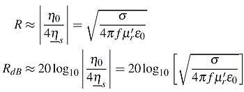
Where η0 [Ω] is the intrinsic impedance of free-space (377Ω), ηs [Ω] is the intrinsic impedance of the shield material, σ [S/m] is the specific conductance of the shield material, f [Hz] is the frequency of the sinusoidal plane wave, μr' is the relative magnetic permeability of the shield material and ε0 is the permittivity of vacuum (8.854e−12 F/m).
Absorption Loss.
The absorption loss A [dB] of a solid shield barrier of thickness t [m] and of good conductivity (α = 1/δ) in the far-field can be approximated as:
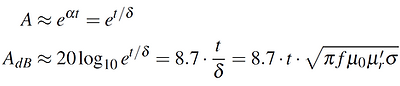
Where α = 1/δ [1/m] is the attenuation coefficient of the shield material, t [m] is the thickness of the shield, δ [m] is the skin depth for a wave with frequency f [Hz], f [Hz] is the frequency of the sinusoidal plane wave, μr' is the relative magnetic permeability of the shield material, μ0 is the permeability of vacuum (12.57e-7 H/m) and σ [S/m] is the specific conductance of the shield material.
Multiple-Reflection Loss Correction
The multiple-reflection loss correction M [dB] must be considered for thin shields, where the absorption loss A [dB] is below 15dB. For a plane wave in the far-field and a solid shield barrier of good conductivity, M [dB] can be approximately calculated as [11.4]:

Where t [m] is the thickness of the shield and δ [m] is the skin depth for a wave with frequency f [Hz].
Example. Shielding Effectiveness PCB (Far-Field!).
The following pictures show the (far-field!) shielding effectiveness of PCB ground planes with thicknesses 35μm and 17.5μm. It can be seen that a thinner ground plane shields as good as a thicker ground plane for frequencies below 10MHz.

Example. Shielding Effectiveness Cable (Far-Field!).
The following pictures show the (far-field!) shielding effectiveness of a typical cable shield with a thickness of 1.5mil. It can be seen that the shielding effectiveness SE [dB] for silver and aluminum is better than compared to tin at frequencies f > 1MHz.

Near Field Shielding.
Let's assume a shield is placed at a distance d [m] in the near field of a noise source and you would like to know the shielding effectiveness. Calculating the shielding effectiveness in the near field area of a source is much more difficult, than in the far-field. This is due to the fact, that the wave impedance in the near field is difficult to determine and it changes significantly with distance d (either with factor 1/d^2 or 1/d^3).
In order to calculate the shielding effectiveness in the near field of a source, it must be known if the source is a ...:
-
Electric field source. High wave impedance Zw [Ω], Hertzian electric dipole. Examples: wires, PCB traces, cables, spark gaps (e.g. DC motors).
-
Magnetic field source. Low wave impedance Zw [Ω], magnetic loop dipole. Examples: current loops, transformers, wireless charging devices.
From the above, we know that the shielding effectiveness is the sum of reflection loss R [dB], absorption loss A [dB], and multiple-reflection loss M [dB]. In the following paragraphs, the absorption and reflection loss of near-field shielding is discussed in more detail.
Absorption Loss.
The absorption loss A [dB] is unaffected by the type of source (near-field, far-field, electric/magnetic field source).
Reflection Loss.
The reflection loss R [dB] is calculated differently from the far-field and depends on the type of source.
-
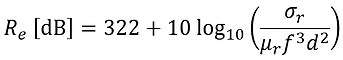
Reflection Re [dB] loss of near field, electric field sources:
-
Reflection Rm [dB] loss of near field, magnetic field sources:

σr is the relative conductivity to copper, μr is the relative permeability, f [Hz] is the signal frequency, d [m] is the distance between source and shield.
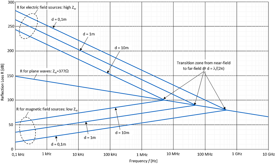
The graphic below shows some interesting facts:
-
Reflection loss Re [dB] of electric field sources in the near-field increases with decreasing distance d [m] from the source. Re [dB] is considerably higher compared to the plane wave reflection loss R [dB].
-
Reflection loss Rm [dB] of magnetic field sources in the near-field decreases with decreasing distance d [m] from the source. Rm [dB] is considerably lower compared to the plane wave reflection loss R [dB].
Slots and Apertures.
Above, we always assumed a perfect solid shield. Slots and apertures are efficient radiators (yes, radiators!) when their maximum linear dimension (not area!) l [m] is equal to λ/2. Therefore, if a slot or aperture has a linear dimension l of λ/2, the shielding effectiveness SE = 0 [dB]. Shielding effectiveness of a single slot with maximum linear dimension l [m] (which is equal to or less than λ/2) and for a signal with wavelength λ [m] is:

If there are multiple apertures, the shielding effectiveness will be reduced even more. We can calculate the shielding effectiveness of a linear (not multi-dimensional!) array of equally, closely spaced apertures n of length l [m], where the total array length larray [m] is less than λ/2:


In the case of a multi-dimensional array of m rows (and m<n !), only the n apertures of the first row have to be considered in case of shielding effectiveness reduction. In other words, the additional rows (2nd, 3rd, ...) will not lower the shielding effectiveness significantly. The shielding effectiveness of a multi-dimensional array of equal size apertures will be the shielding effectiveness of one single hole, minus the shielding effectiveness reduction of the first row of n apertures (-20log10(√n)).
The shielding effectiveness reduction due to a linear array of n apertures (relative to a single aperture) is shown in the graph below. Be aware that the array length larray must be smaller than λ/2, otherwise the SE is 0dB.
Apertures located on different surfaces, which all look in different directions, do NOT decrease the overall shielding effectiveness, because they radiate in different directions.

Magnetic Field Shielding @ Low-Frequencies.
From above we learned that the most difficult field to shield is a low-frequency magnetic field. This is due to the fact that the reflection loss R [dB] and the absorption loss A [dB] are low for low-frequency magnetic fields.
There are these two methods for shielding against low-frequency magnetic fields:
-
Shield with μr >> 1. Use of a low-reluctance shield material with a high magnetic permeability μr >> 1 (e.g. nickel, Mu-metal).
NOTE: The permeability decreases with increasing frequency f [Hz] and with increasing magnetic field strength H [A/m] or magnetic flux Φ [Wb] respectively.

-
Shorted turn. Use a loop conductor which is placed in the magnetic field. The induced current iind [A] in the loop conductor will generate a counter magnetic field which will then lower the magnetic field in the vicinity of the loop.

References:
[11.2] Dr. Todd H. Hubing. EMC Question of the Week: 2017-2020. LearnEMC, LLC, 2021