8 Skin Effect
The resistance per unit length [Ω/m] for direct current (RDC') and for alternating current (RAC' ) of any conductor can be written as [8.1]:

ρ = specific electrical resistivity of the conductor material [Ωm]. σ = specific electrical conductivity of the conductor material [S/m]. A = cross-sectional area of the conductor [m^2], Aeff = effective cross-sectional area of the conductor through which the current effectively flows [m^2].
For direct current (DC, 0 Hz), the area A [m^2] is equal to the complete conductor diameter. However, for alternating current (AC) with frequency f [Hz], the magnetic fields produced by the current in the conductor forces the current to flow towards the outer surface of the conductor. The higher the signal frequency f [Hz] the smaller the cross-section Aeff [m^2] through which the current effectively flows.
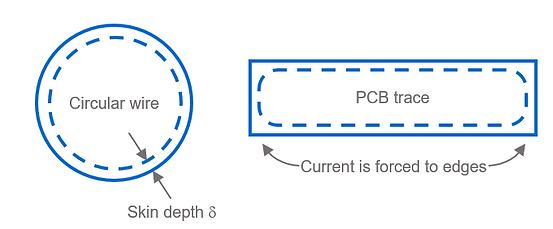
As a consequence of the skin effect, the resistance of a conductor increases with increasing frequency.
The diagram below shows RAC' [Ω/m] of a round copper wire with an outer diameter of D=1mm and a copper PCB trace with width w=0.25mm and height h=0.035mm (1oz). The calculations for RAC' [Ω/m] are approximations and ignore the return current path (proximity effect) and assume a single conductor surrounded only by air. However, the diagram gives an idea of how the skin effect influences the resistance at higher frequencies.

Introduction and definitions of the term skin depth δ [m]:
-
Conductors: The skin depth δ [m] is defined as the distance from the conductor edge where the current density has fallen to 37% (37% = 1/e = 1/2.72) of the current density at the surface of the conductor J0 [A/m^2]. The current density Jd [A/m^2] at distance d [m] from the conductor surface is defined as [8.2]:
-
Shielding: Imagine an electromagnetic plane wave of field strength E0 [V/m] and H0 [A/m] entering an absorbing material (shield). The skin depth δ [m] is the distance an electromagnetic wave has to travel through that absorbing material until its field strength is reduced to 37% of E0 [V/m] or H0 [A/m] (37% = 1/e = 1/2.72). This means that the power of the plane electromagnetic wave is lowered by 20·log10(0.37) = 9dB after it traveled the distance δ [m]. The attenuation of an electromagnetic plane wave is defined like this [8.2]:

Ed = remaining electric field [V/m] strength of a plane wave with field strength E0, after traveling distance d [m] through a medium with attenuation constant α [1/m]. Hd = remaining magnetic field strength [A/m] of a plane wave with field strength H0, after traveling distance d [m] through a medium with attenuation constant α [1/m]. Remember that γ = α+jβ is the so-called propagation constant.

From above, you know that the skin depth δ [m] is defined as the inverse of the attenuation constant α [1/m] [8.3]:

For good conductors (with σ>>ωε), the skin depth formula can be simplified to [8.2]:

Where f [Hz] is the frequency, µr [1] is the relative permeability of the conductor, µ0 [H/m] is the absolute permeability and σ [S/m] is the specific electrical conductivity of the conductor material.
Below are some example values of skin depths for silver, copper, gold, aluminum, nickel, iron, and stainless steel 316. NOTE: Important to know for calculation of skin depth of nickel, iron, stainless steel, and any other ferromagnetic metal:
-
Relative permeability μr [1] depends on the specific material and alloy (therefore, be careful when reading our table and graphic below).
-
Relative permeability μr [1] depends on the frequency f [Hz] (neglected in the table and graphic below).

